|
|
|||||||||||||||||||||||||||
ThrustersIt took the longest time to decide if I should buy trolling motors for thrusters or convert DC motors for the job, but the agonizing is over. My final choice was a 36 volt Minn Kota trolling motor that produces 101 lbs of thrust. Below are the details about the Minn Kota as well as the other options I explored. Minn Kota - 101 lb thrust. - My ChoiceMinn Kota makes the RipTide with 101 lbs thrust, on 36 volts, that draws 46 amps at full power. The RipTide is a salt water version, but there is nothing different about the motor so don't pay more for the model name. Minn Kota rates the motor at 1.79HP. In late 2007, www.trollingmotorparts.com was selling the lower unit (Part # 2316285) for $220 each, the speed controller assembly (Part #2774003) for $129.95, and the props (Part #2331160 ) for $36.95. This is a standard pitch prop which for trolling motors is always designed for power and not speed, which is perfect for a sub. The top speed would be around 5 mph for a typical boat. I hope to get 3 mph. The total price for each thruster is $388 or about $800 for both with shipping. As a bonus I discovered after I got my motors working that they had a dual ramp reversing feature. They means that when you instantly switch the motor from forward to reverse that the speed controller automatically modifies your command into; slow to a stop and the speed up to the selected speed in the other direction. They prevents damage to the motor and big spikes in the amperage. There are a couple of things to consider when selecting a trolling motor to be used on a sub and the most important is how you plan to keep the water out. The problem is that the lip seal or o-ring that the manufacturers put around the drive shaft is not intended to work at 120 feet. The options include filling the motor with oil which will not compress and so it prevents the seal from leaking. A small flexible hose can be tapped into the motor housing and also filled with oil so that it acts as a reserve for any air trapped in the motor housing. If the oil pressure inside the motor housing is the same as the water pressure outside then the seal will not know that it is 120 feet below the surface. My choice is very similar, except that instead of oil, I will simply supply ambient pressure air to the inside of the motor. If you do compensate the motor with oil or air you will have to select a motor that does not have any electronic components inside the motor housing. Many manufacturers are now building speed controllers inside the motor housing and these parts will not survive the pressure changes. Others have also successfully replace the seal in
the motor with a seal that is capable of withstanding the pressure
at the operating depth. Parker Seals manufactures a full line
of lip seals under the name FlexiSeal. This can be configured
to work to 1000 feet. The draw back is that you will need to
machine the motor housing in order to provide the proper seat for
the seal, and the deeper you go the more these seals will squeeze
against the shaft and the more HP they will rob from the motor.
Parker Seals at www.parker.com
has a inquiry form on their web site that you can fill out and
submit, and they will help you select the best seal for your
project. Other Thruster Options That Were ConsideredMinn Kota - T90I already have one 12v , 42 amp max, 40 lb thrust Minkota T90 trolling motor and a new one lower unit will will cost $115 for the motor, $30 for the prop and $25 for shipping from www.trollingmotorparts.com. This would be the low cost approach with an easy upgrade if needed for the batteries but these units do not include speed controllers so they would be on or off. Speed controllers could be added but the would cost $140 each. The batteries could easily be reconfigured from 12v to 36 volt but the rest of the investment would not be recoverable. In the end, considering the size and weight of the craft, I think the price of the 101 lb thrust motors is worth the price. When a rock or tree appear from out of the gloom, the extra maneuvering power will be appreciated. MotorGuide - Great WhiteAnother contender at 105 lbs and 48 max amps is the is MotorGuide
with has been acquired by Mercury Marine but the motors are still
made right here in Tulsa, Oklahoma. While not popular in personal
submarines, they are used by Torpedo Inc
www.torpedodpv.com, to make
scuba tows. Having talked at length with Tim Hager the Product
Manager at MotorGuide there is a problem in that the speed
controller circuit for the Great White is located in the lower unit
or the power head. That makes sense for cooling but it makes ambient
compensating the Great White impossible because the capacitors and
IC's on the controller board will crush under pressure as they are
only thinly potted to protect them from moisture.
Click here for
the Great White, SW109, Schematics. Off-The-Shelf (almost) Twin ThrustersWhile chatting with Tim, the product manager at MotorGuide he suggested a product from their partner Lenco Marine called Joy Ride. You would have to put 1 ATM seals in the motors to protect the circuits because they are MotorGuides but it's a good off-the-shelf twin thruster solution. Go to www.lencomarine.com and look for "Joy Ride". I think he said $2,700 for the package. The motors are mounted on trim tabs controlled from the same joystick, and if mounted upside down the down on the joystick button would pivot the motors down on a sub. Building the Thruster from ScratchDC Motors come in brushless permanent magnet, brushed permanent magnet, shunt wound and series wound. The best choice is brushless permanent magnet because there is no need for maintaining the brushes but they are very expensive. A good choice is brushed permanent magnet and shunt wound types. The poor choice is series wound, because of their poor efficiency at low speeds. Also, not all motors are reversible. The you have to find a prop that will put the proper load on your motor with a good balance between speed and power. You might even look a speed reduction gears so you can use a bigger and more efficient prop. After all that you're going to need to build a housing and then add on a speed controller. If it all sounds like a lot of work, then you have the picture. As a starting point I was looking at the Ohio 13065
which was recommended by 4QD. They say "This is a 1HP motor with a C56 size frame. It is one of our
favorite motors for test purposes. Although 'rated' at 41 amps, 24v,
we regularly use it to test Pro-120 controllers and several US
customers use it with our 4QD-150 and even 4QD-200 controllers,
though we suspect the -230 amps (typical max current) from the
4QD-200 is possibly pushing even this motor a bit far! However it is
an extremely conservatively rated motor. If Ohio's other motors are
equally conservatively rated then they are to be thoroughly
recommended." Speed ControlIn order to run slower, most small trolling motors simply reduce the
voltage going to motor by sending it to a resistor where it becomes
heat. It easy to do, but your valuable energy in the battery is
wasted. A pulse width modulators (PWM) uses electronics to quickly
turn the power off and on to the motors. To make the motors run
slower, the power is just left off a little longer. In a good speed
controller the power will be turned off and on over 20,000 times
each second so the motor hardly knows what is happening. The slower
you run the motor the more time the motor is actually powered off,
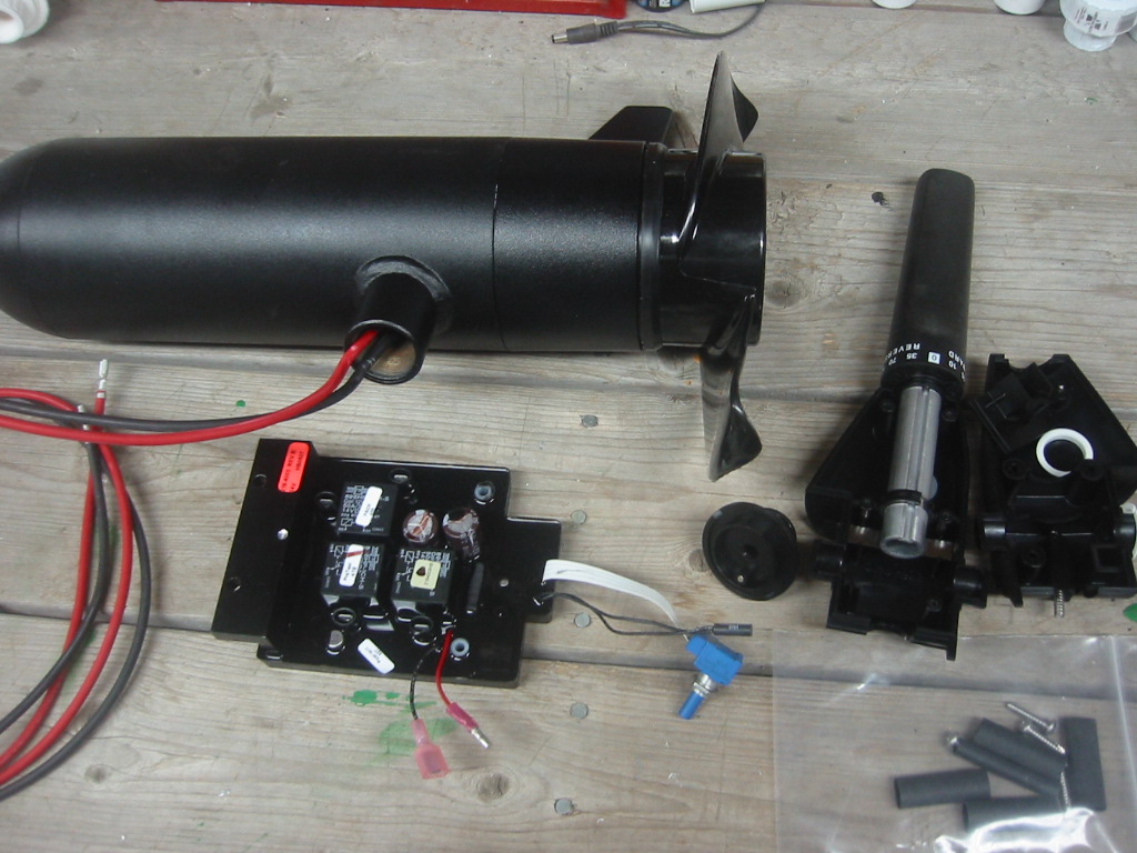
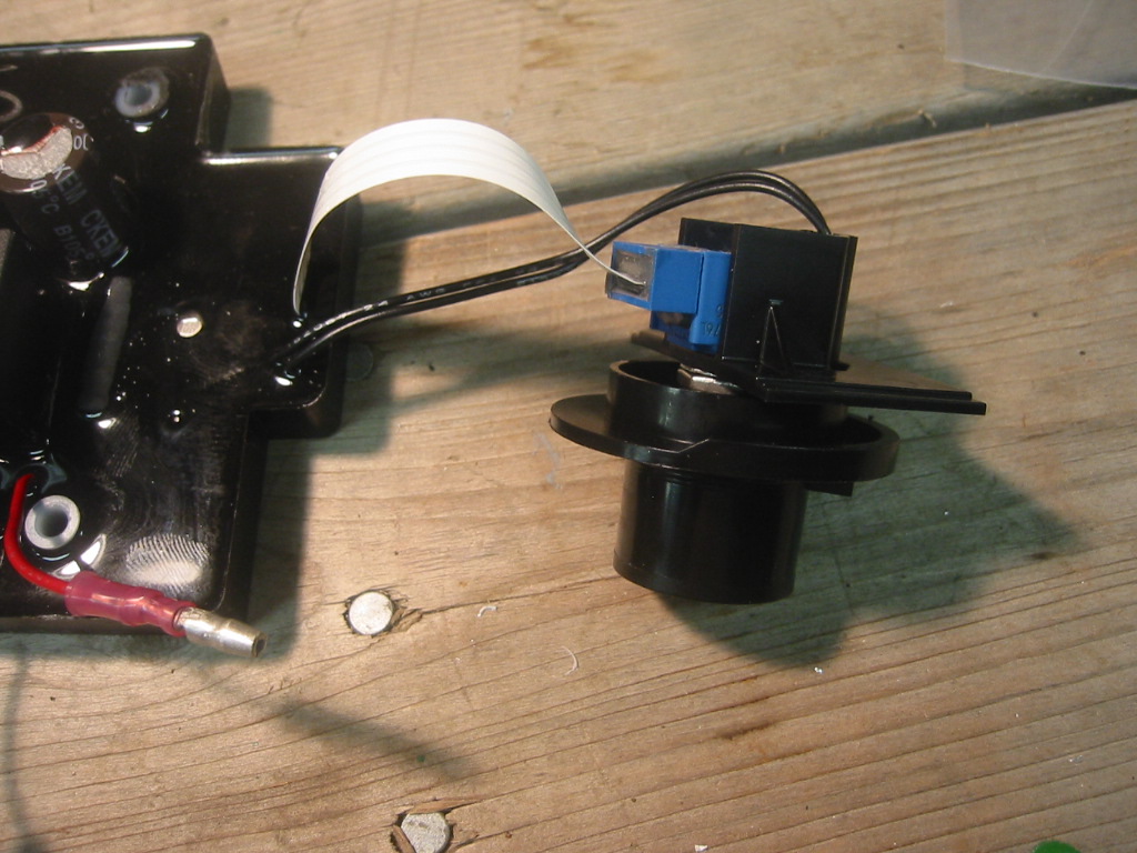
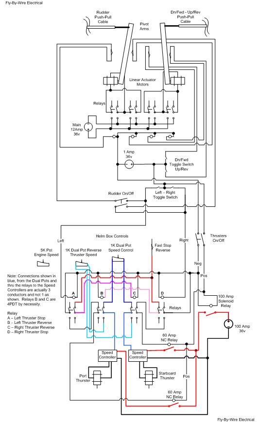
and the power is not wasted. Wiring the Minn Kota Thrusters
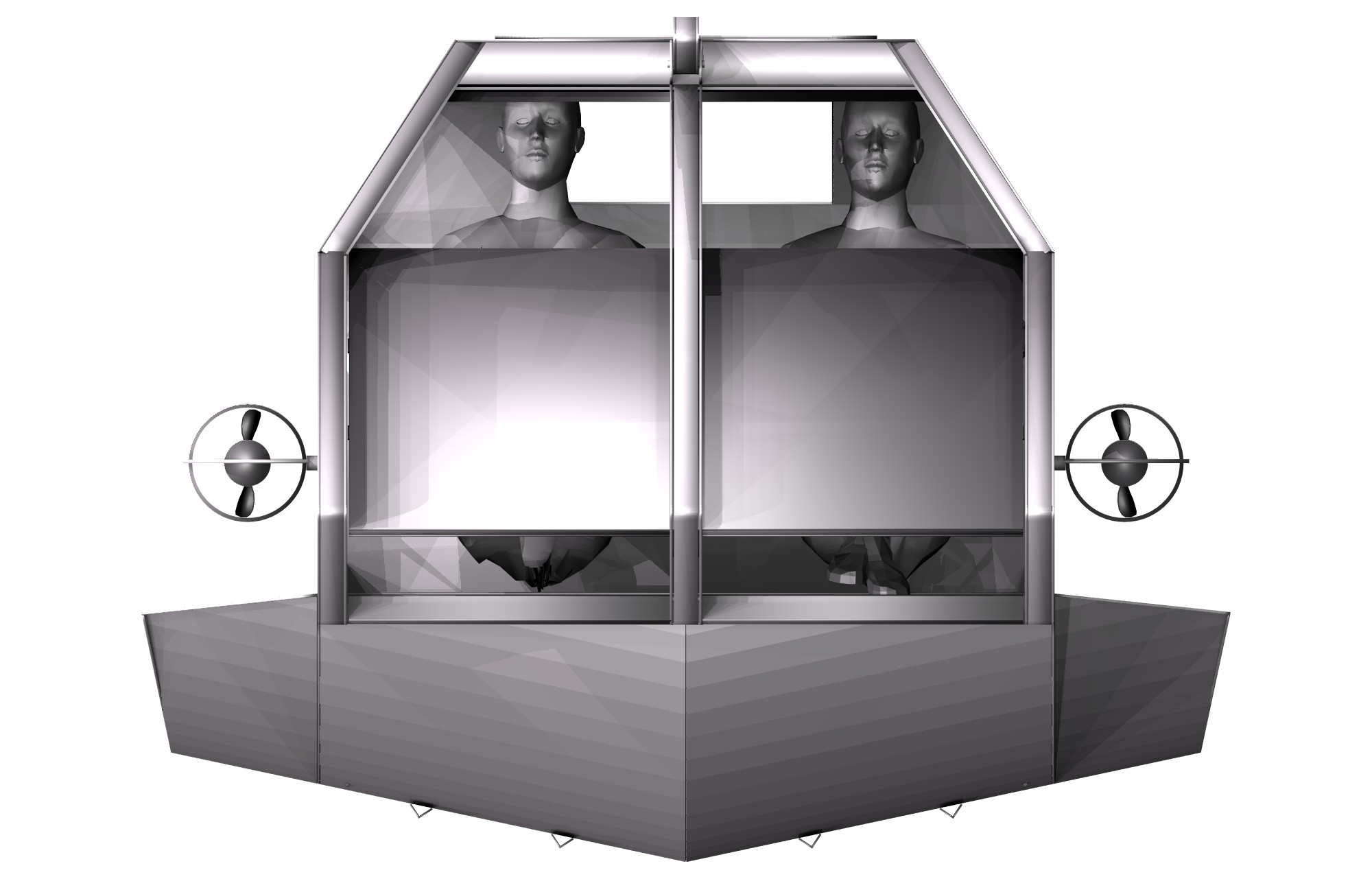
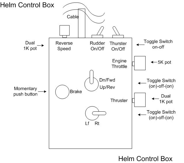
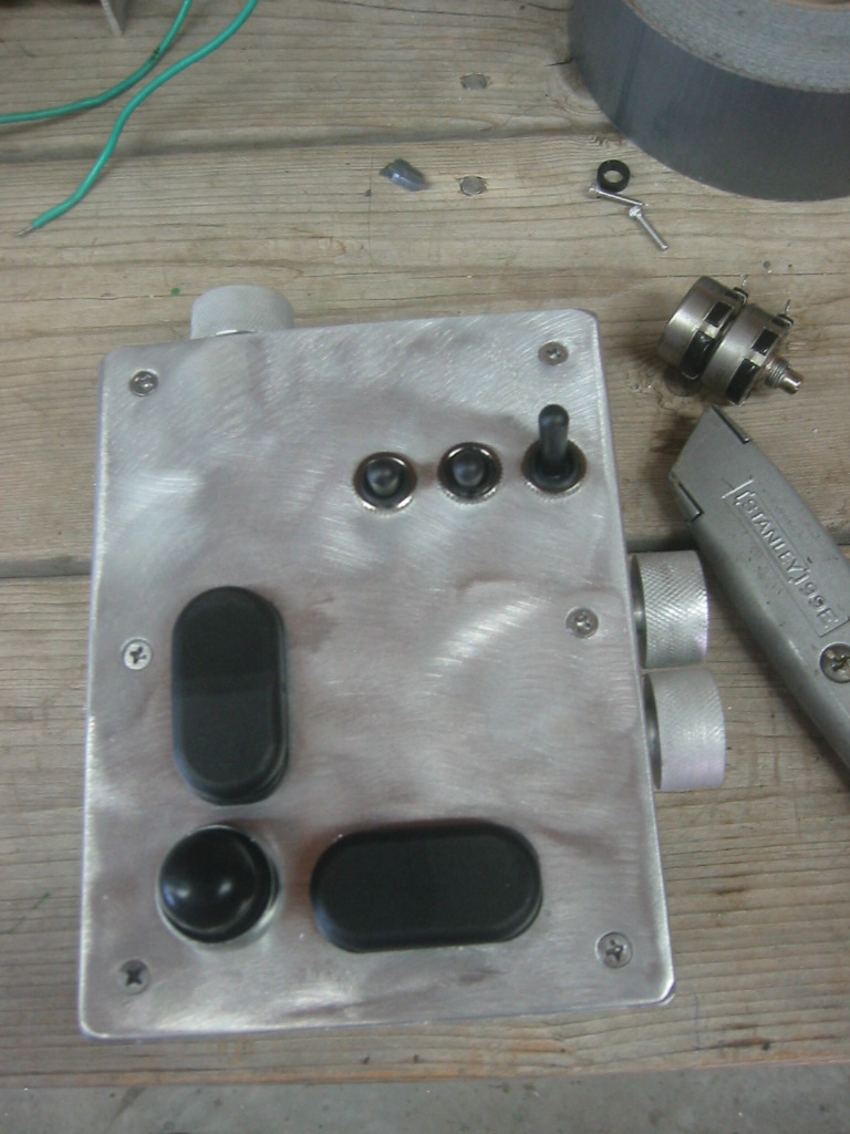
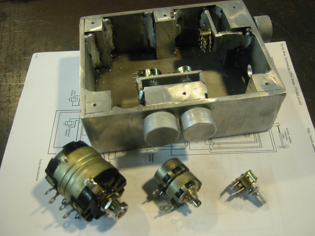
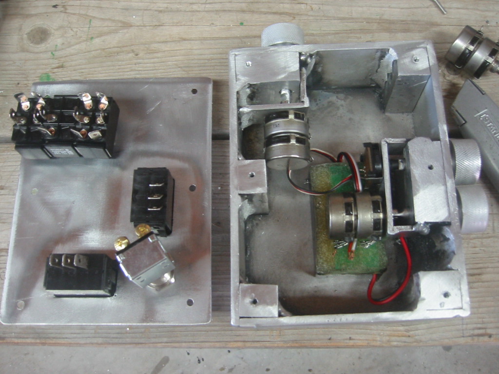
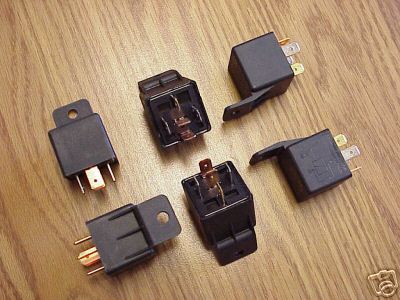
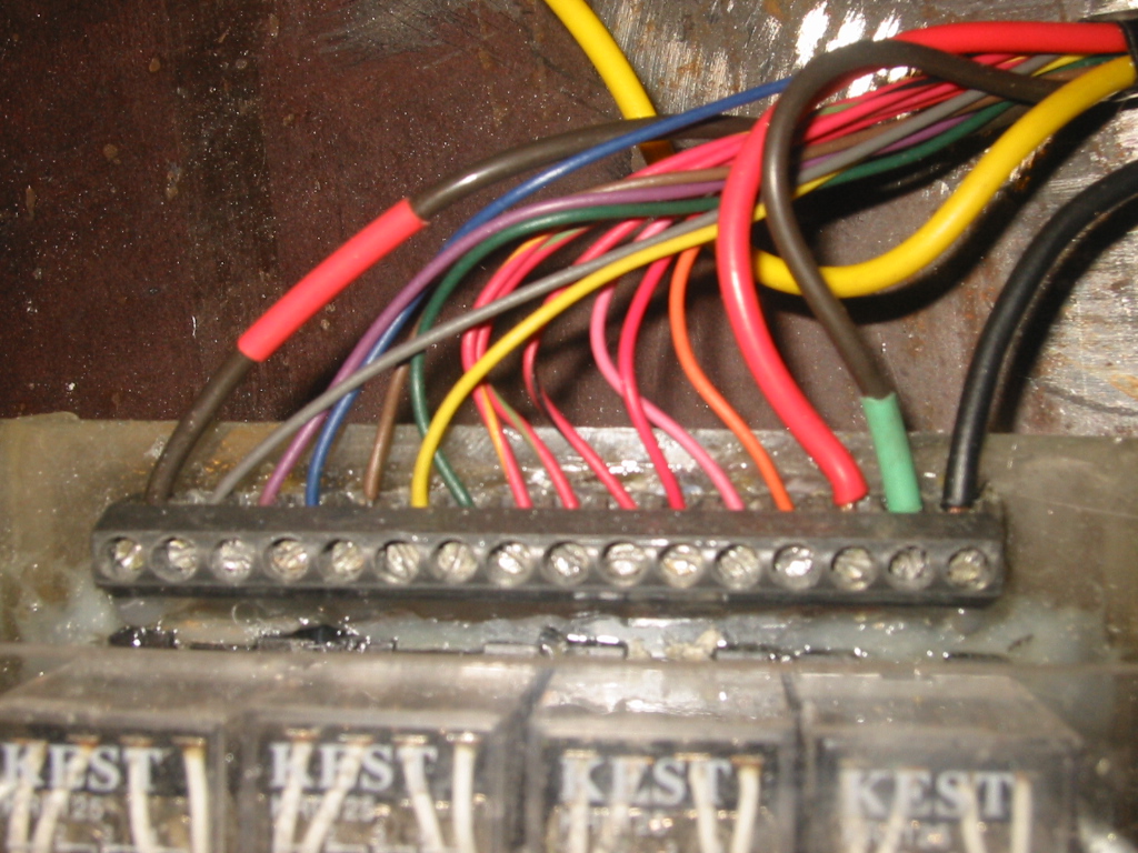
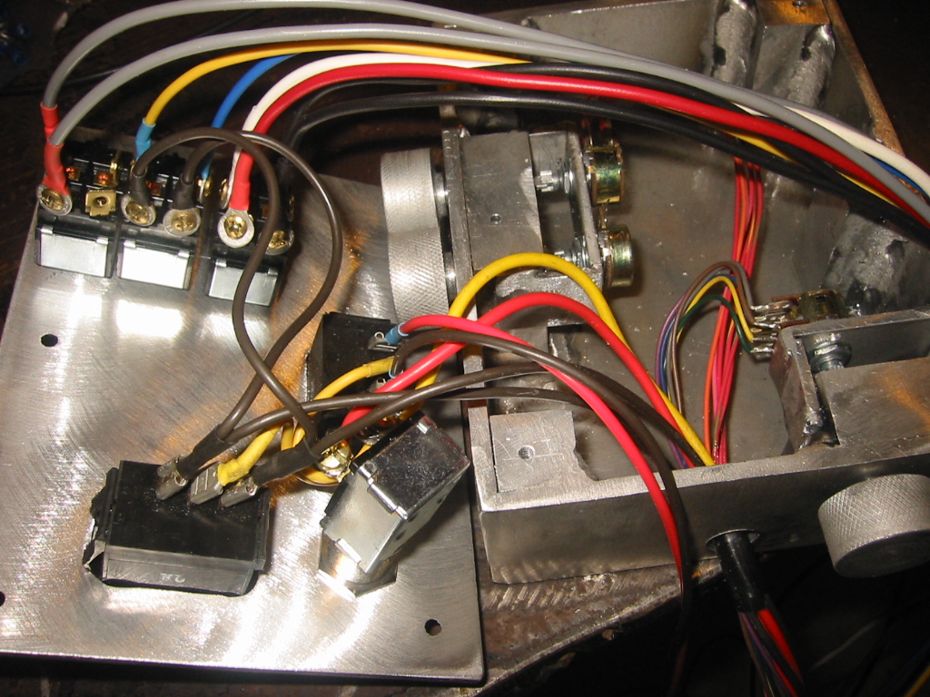
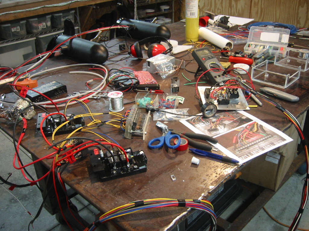
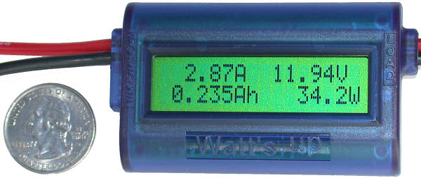
What I Got(1) There is not much to the wiring as shown in the diagram. Click here for the complete motor and wiring diagram. I originally planned to seal the electronics in a 1 ATM housing and compensate but it turns out that there are no serviceable electronic parts on the board so I ended up just encasing them in epoxy. (2) The parts have arrived. The handle comes with the speed controller as well as some heat shrink tubing. There are just 2, 10 awg wires that run from the speed controller to the motor and the speed controller only needs power connected to it from the batteries. Forward and reverse is controlled by a single 1K pot with an 300 degree rotation. At the center point a magnet triggers a Hamlin 59020, "normally open" magnetic reed switch. I originally thought that this switch would shut the motor off in order to make a gentle turn. But after some trial and error I discovered that this switch only only shuts the motor off when the speed setting for the pot is very close to zero. Since the motors consistently shut off when the pot is centered without the magnetic switch I simply ended up leaving it out. What I Needed(4) The thrusters will be mounted on either side of the sub and connected by a drive shaft that passes from one side to the other just behind the cabin. (5) A helm control box in the cabin will allow both of the thrusters to be controlled a one unit. (6) Only one knob on the side of the helm box controls the speed for both thrusters. To do this the single 1K pot that comes with the motors is replaced with a dual pot that both speed controllers will connect to. One rocker switch on the bottom center of the box controls left and right turns. To turn left the thruster on the left side is simply stopped and the thruster on the right side is allowed to push the boat forward and slowly to the left. There is a button for braking on the bottom left corner of the box. If the sub is not turning then pressing the button will reverse both thrusters. Another knob connected to a second dual pot is on the top of the box. It controls the reverse speed that is used when the brake button is pressed. If the sub is turning, for example to the left, then the left motor will not be running. However if the brake button is then pressed the left motor will start running at the reverse speed which will cause a tighter turn to the left. How I Did It(7) (8) The dual pots used to control both thrusters is simply two pots that share the same shaft. When I got to the point were I could do some testing I discovered that all dual 1K pots are not the same. The ones I found on ebay were out of sync by a much as 300 ohms. The result is that when one thruster stopped, the other was still running. There really good pots are available from www.mouser.com, but I don't want to by 500 of them, so I going to try some lower priced end units from www.futurlec.com and www.surplussales.com to test my luck again. The results are in and it reinforces that the old saying "You get what you pay for." sometimes is just a sales pitch from someone fighting globalization. Because the 90 cent, dual pots from www.futurlec.com shipped directly from Asia have less that 1% error. With the two dual pots controlling the forward and reverse speed for both thrusters, the next step was to connect the correct pot the the correct speed controller and also cut the power to either speed controller using relay switches. (9) The bottom half of the helm wiring diagram is the wiring show 7 relay switches along with the 2 speed controllers and 2 dual pots. A 100 amp relay controls all power to the thruster system. (10) Two 60 amp relays allow power to be cut to one thruster or the other for making gentle turns. I found the relays for $20 each on eBay. These are SPDT automotive relays that can handle 60 amps so the price is considerably higher that your standard 30 amp auto relay, but they will easily carry the 45 amps needed by the thrusters. (11) A home-make relay block holds 4 Pole Double Throw (4PDT) relays. Three of the poles are used to switch the three wires used by a pot from the pot with the forward speed to the pot with the reverse speed. The 4th pole in the relay is used to enable or disable the other relays depending on the position of the break button and the left and right rocker switch in the helm box. (12) The wire for the pots only travel about 6 feet from the helm control box to the relay block and the amperage on these is measured in milliamps so only very small 22 awg wire is needed. You might notice a crossover connection between the left right rocker switch and one of the toggle switches on the top of the helm box. This toggle switch allows for left and right turn request to be optionally passed along to the jet pumps' rudder. When operating submerged the rudder will have little effect but can be positioned and then turned off so that it can be used to control trim. (13) All of this mess was put together on the work bench where assumptions about dual pots, and how the wiring on the speed controllers was put to the test. On the work bench you may notice the color print outs for photos showing the wiring. I find this to be an excellent substitute for trying to write all of those wire colors and terminal descriptions down on a diagram. Especially since the paper and pencil method is very prone to errors. (14) The last piece to the wiring is a digital Amp hour meter
that will monitor the amount of power used by the 36 volt system
which includes the thrusters and the motors that control the rudder
and dive plane angle. The "Watt's Up" meter also reports battery
voltage, minimum voltage sags, and peak amp usage. Best yet, it cost
less than $60 since they manufacture lot of them for the RC hobby market .
(15) The "Watt's Up" is rated for continuous duty at 50 amps which is more than half
throttle but in the process of water proofing the unit, I removed
the case and replaced 12 gauge wire with dual 10 gauge wires and
left the solder connections and shunt exposed to the air. The
larger wire will act as an excellent heat sync. Mounting the Minn Kota Thrusters
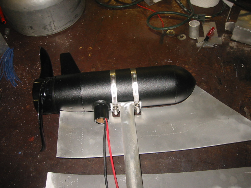
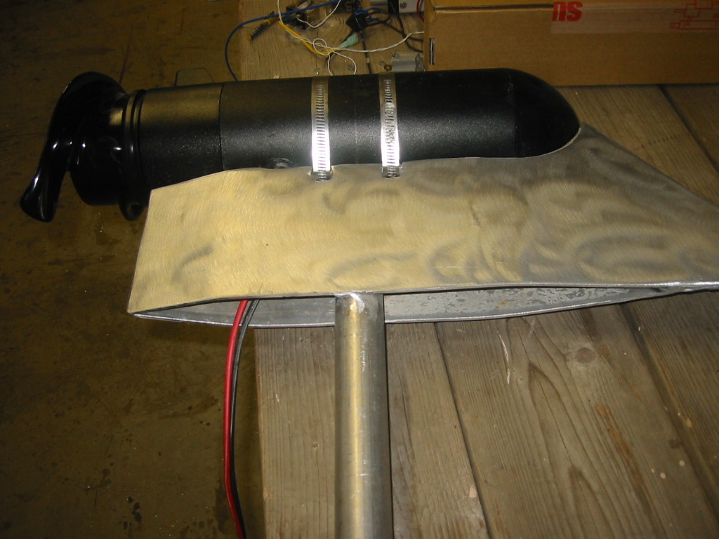
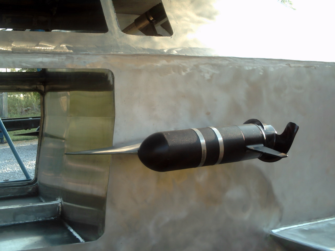
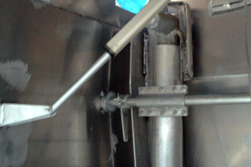
(1) (2) In order to mount the motors onto the sub I welded a small rectangular plate onto the end of a pipe and used hose clamps around the motor to secure it to the plate. I then cut and formed 1/8" aluminum sheet shroud the pipe top and bottom. This shroud will act as small dive plane, divert snags outside of the motor and hide the ugly connection. I did not use the normal threaded shaft connection point because it is behind center of gravity and it would place unnecessary load on the push-pull cable that will rotate the shaft and pitch the thrusters. (3) The thruster shafts mount to the hull just behind the cabin wall. (4) Each shaft passes through nylon bushings, aka kitchen cutting board, that are held in place with inside a 1" long piece of pipe that is welded to the hull. A piece of PVC pipe acts as a bushing between the thruster housing and the outside surface of the hull. This electronically isolates the thrusters from the hull so that it is not possible for the 36 volt system to short against the hull. The shafts from each thruster are coupled together and a electrically isolated control arm is clamped to the shaft that will connect to a push-pull cable which ties it into the helm actuator box.
|
|||||||||||||||||||||||||||

