|
|
||||||||||||||||||||||
Landing Gear
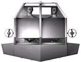
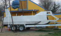
The bottom dive hatches can be opened anytime the sub is submerged but exiting the sub will only be done when the sub is resting on the bottom. The reason for this is that when one diver exits water will flood into the bottom to replace the divers weight, but ambient air will continue to flow into the cabin and the water will soon be displaced making making the sub rise. By setting the sub on the bottom, the trim tanks can be flooded and the ballast sled brought all the way forward to compensate for the weight of the divers. When sitting on the bottom the is enough room for the hatches to be opened but it's a tight squeeze. Many subs have skids that keep them off the sometimes muddy bottoms and also makes it easier for them to use bottom hatches. Since skids would make planning almost impossible the boat needs retractable landing gear to support it. So four independent supports will make using the lower hatches easier and they will also allow the boat to maintain level keel on a gently sloping surface. I went back and forth several times with different designs until I finally settled on using linier actuators for the job of raising and lowing the legs. First DesignI first intended to convert windshield wiper motors to power the legs up and down by driving a sprocket and chain attached to the top of the support. The support would extend through the bottom of the boat. When in the full up position the foot of each support will seat against a neoprene. The support will be constructed from 2" aluminum pipe and extend up to 24 inches through the bottom of the hull. The support would have a flat foot which will seal against neoprene on the bottom when fully retracted. The support would also have 1/2 inch holes drilled into it to allow water to flood the support and enter the hull. This will allow for gear to be partially lowered in order to assist in flooding the hull for dives.
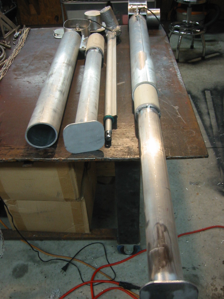
The controls for the motors will consist of 1, 2 position DPDT toggle switch to control direction, and 4, combination on-off switch and circuit breaker. When the legs are fully extended or retracted, or when they encounter significant resistance the motor load will trip the circuit breaker. Windshield wiper motors are well suited for the task because they use a worm drive gear which will effectively lock the support in position once the motor is powered off. After experimenting with a lead screw for moving the ballast sled, I have now had second thoughts about this design and I am going back to a previous idea of using a more traditional screw jack design. Basically the motor will turn and all-thread that is inside the leg and threaded through a nut that is attached to the leg. An Acme lead-screw from McMaster would have less friction but they are expensive and my apprehension for this design is that dirt and sand will reap havoc on the threads. This does kill the idea of using the leg for an additional way to flood the hull. With a chain drive I could cut flood holes in the legs but with threads in the leg I will want to avoid all of the sand and mud that would enter the leg when it touches down on the bottom. On the up side, it will require fewer parts so if it works reliably I will come out ahead, if it works pretty good then I'll try lead screws, and if it sucks, I'll go back to a chain drive. Changed my mind again. Decided to go with square tubing in place of round so the outer sleeve could rise above to the top of the leg and prevent flooding if it became necessary to remove the leg. That being the case I would not be able to place a guide on the inside leg which would have prevented it from turning with the all-thread, so it is necessary to use square tubing in stead of a guide. The inside leg will have the lead screw nut cast in an aluminum block that will be fixed to the leg with screws so it can be replaced if needed. The rest of the inside leg will consist of a 1 inch aluminum round tube inside of an 1 3/4 inch square aluminum tube with 1/8 inch walls. The space between the round tube and the square tube will be filled with cast aluminum for reinforcement. The leg sheathe will be a 2 inch by 1/8 inch wall, square tube, welded to the bottom hull extent up to the drive motor at the top. The will allow for the movable support leg to be removed without allowing water the inter the hull.
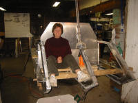
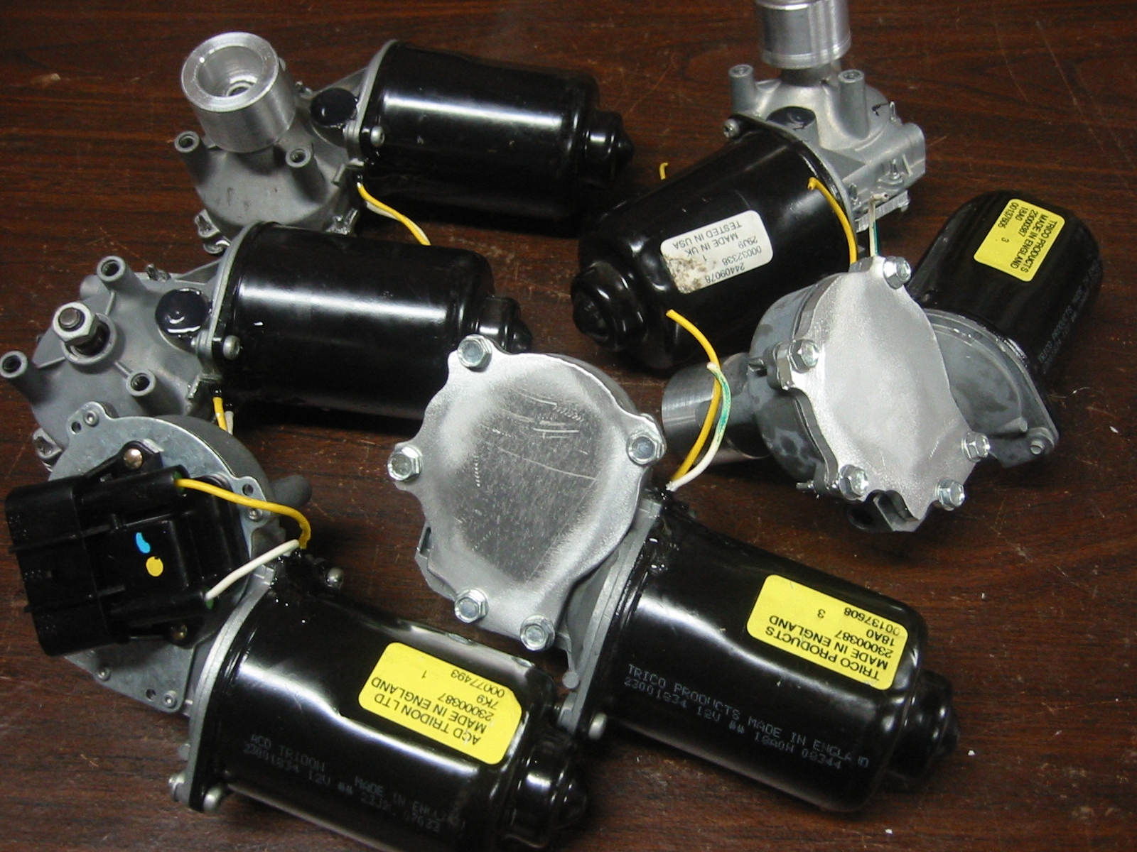
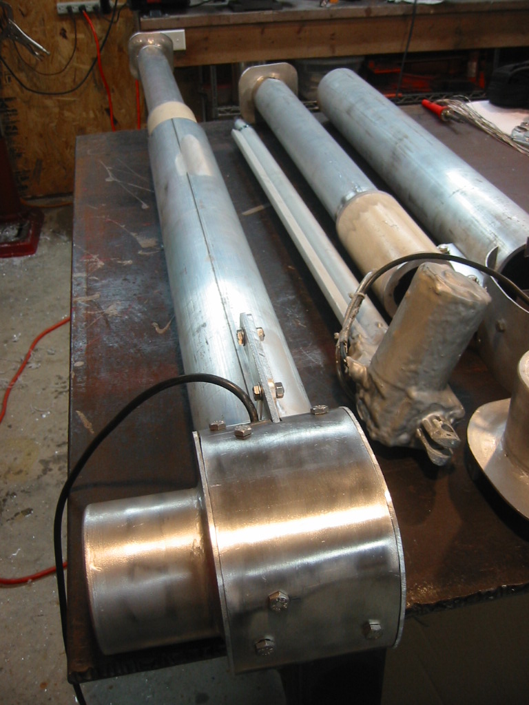
The drive motors are converted windshield wiper motors. The turn about 80 rpm with lots of tork. The leg will not move fast but hopefully the motors will be able to overcome debris that will surely work their way into the threads. Converting windshield wiper motor for submersible use only requires replacing the back plate and position sensor with a solid plate and plugging one vent and the power line connection with epoxy. I could actually purchase actuators and compensate these with ambient air or even oil in order to maintain natural buoyancy. But they cost from $300 to $600 each depending on load and material. My design will be open and exposed to the elements so maintenance will always be necessary, but the will less that $50 each. Of course they will take weeks to build and come with no warrantee. What I actually DidAfter an 18 month break to build a house and shop, I am back to work on the sub, and while the price of something's I was planning to buy has gone up the price of something's I was trying to avoid buying as come down and linier actuators from www.firgelliauto.com and other suppliers are relatively reasonable thanks much in part to the demand custom car parts.
(1) A 12 volt DC, 30 inch stroke, 400 lb (Static) load, aluminum shaft, linear actuator, with fixed limit switches from www.firgelliauto.com is selling for $130. That comes to $580 for 4 units with shipping. I may have to modify the limit switch to make it water proof, but the motor will be easy enough to wrap in fiberglass and compensate with ambient air. The hull will need to be altered some too because with an overall length of 37 inches the units will need to stick out above the rear deck.
(2)
Thanks to my wife Kay, the actuators now have several coats
of epoxy sealing the motor housing. A small plastic air line
was tapped into the motor housing before the epoxy was applied
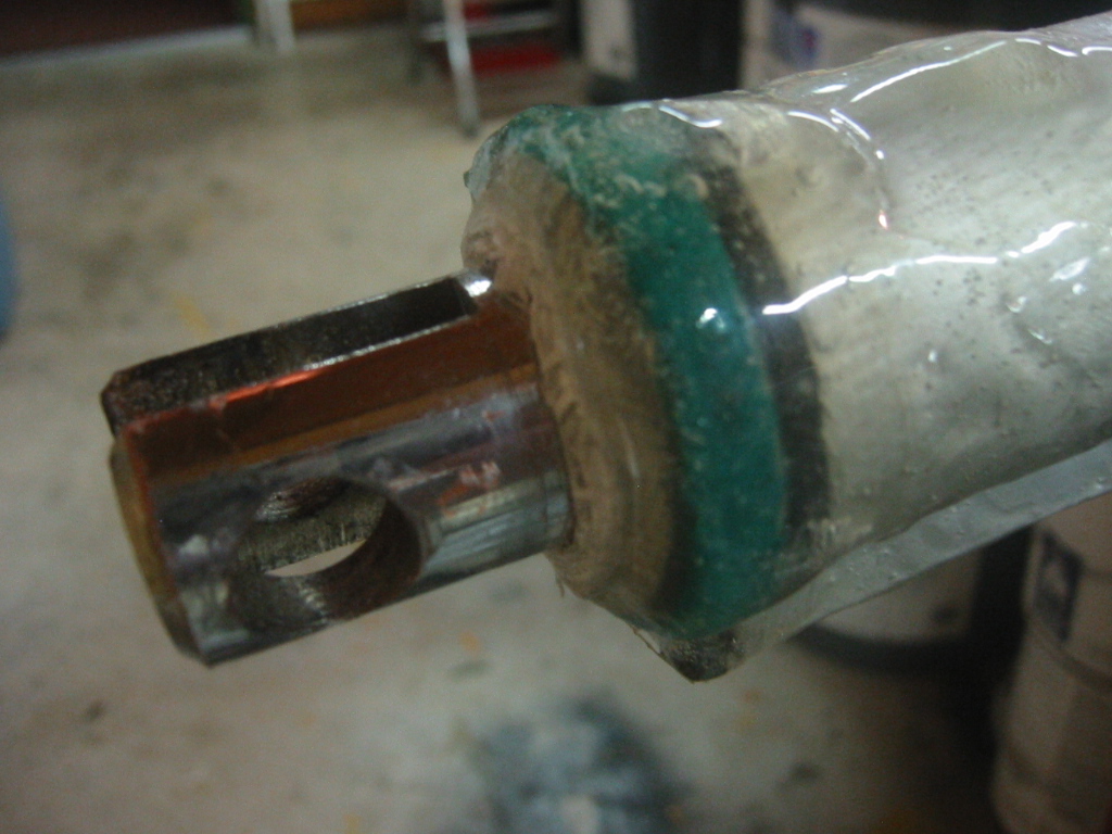
and it will be connect to the ambient air system. (3) A lip seal
has also been glued in place where the actuator shaft extends
from its housing. The lifting load capacity of is more that
sufficient to support the submerged weight of the sub, but their
ability to withstand lateral force is poor. The moving shaft
must be protected from nicks and scratches that would cause the
seal to fail. And finally if a support should fail or need to
be removed it is best if the absence not leave a gaping hole in
the bottom of the hull.
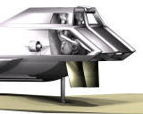
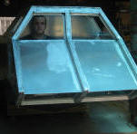
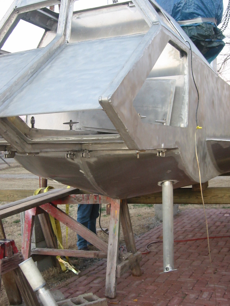
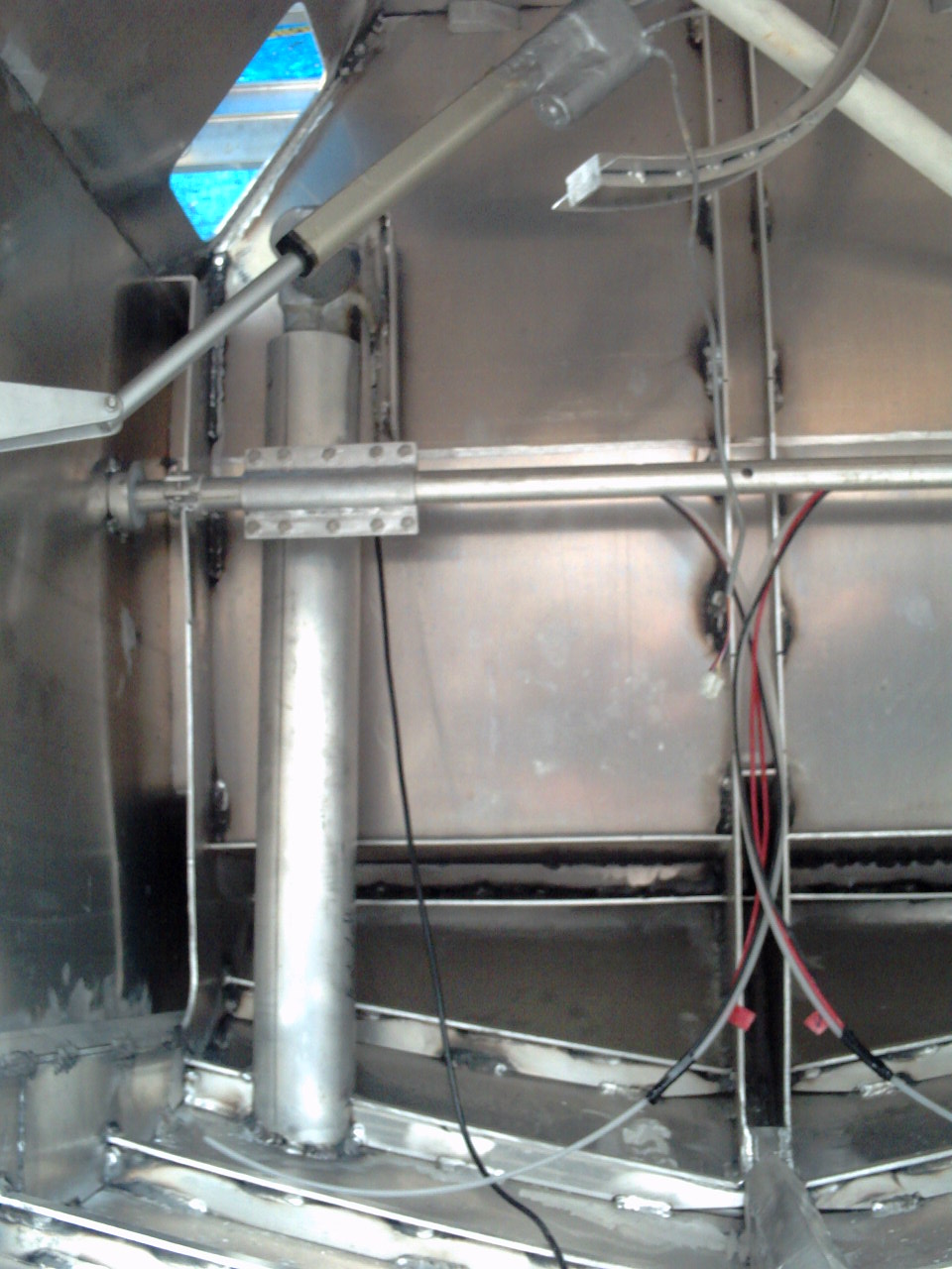
(2 - 6) All of these problems are solved by installing the actuator inside of a 2 1/2" Sch 40 aluminum pipe and letting it move that pipe section up and down through a 3 1/2" section of pipe. The larger 3 1/2" diameter pipe will be welded to the bottom of the hull and rises up 33" so that the top on the pipe will be at the water line when the rear deck is awash. A support bracket fixes the linier actuator at the top and the bottom, end of the actuator is bolted to a foot that is welded on the lower end of the 2 1/2" pipe. The gap between the two pipes is filled with a bushing that allows the inner pipe to slide easily through the outer pipe but which prevents more that 1 inch of play in the leg even when fully extended. Due to the locations of the limit switches, only 2 1/2" of the bushing remains in the outer pipe when the leg is fully extended, but the need to fully extend the legs will be rare as less than 20 inches is needed to allow for the bottom cabin hatches to be opened for easy access into and out of the water. That bushing is made from aluminum retaining rings that are spot welded in place at either end. Next is two rings of nylon plastic, aka $2 cutting board from Target. These actually wear the most against the outer pipe. Between the nylon rings is a 7" section of 3" PVC Sch 40 pipe. There is a gap between the 3" PVC pipe and the inner 2 1/2" aluminum pipe and that was filled with epoxy. A housing made from 1/16" sheet aluminum, 1/8" sheet for the ends and more 3 1/3" pipe. Its held together with 1/4" bolts that are threaded into tapped holes in short pieces of 1" angle that are stop welded to the actuator support and the 1/8" end plates for the housing. (7) The forward legs are installed against the back of the cabin bulkhead. (8) The rear legs are mounted at the front end of the engine compartment. It at first seems like an odd choice as opposed to the rear end of the engine compartment and so closer to the rear of the sub but it is actually a better location mainly for the reason that it places the rear and front legs closer together. In doing so we can more easily land and level the sub on a steeper incline. If the front and rear legs were further from each other it would be necessary to lower one set or the other more in order to maintain a level keel when coming to rest on the bottom. After cutting the holes in the bottom of the hull the tops of the outer tubes were welded into place. The top of the tube is welded to the back side of the cabin bulkhead about 16 inches beneath the roof. The next step was the install the 34 inch linier actuator, but it was not clear to me until I was climbing into the hull with the linier actuator in hand, that you can not put a 34 inch linier actuator in to a hole that has a ceiling 16 inches above it. Perhaps I should say the new view ports into the front trim tank for for ease of inspecting the compartment, but that is not the truth.
|
||||||||||||||||||||||